Agasio IP Cameras are designed and equipped primarily for local and remote purposes such as home or office security surveillance. We provide a variety of products suitable for any type of surveillance system setup, including wired/wireless IP outdoor bullet cameras, IP outdoor dome PTZ cameras, and IP Indoor PT cameras.
Please check the packaging to make sure you have received all items including the camera accessories as follows:
- Agasio IP Camera - Wi-Fi Antenna (If Wi-Fi compatible) - Power Supply - Installation Driver CD - Mounting BracketNote: Please contact us immediately if there are any damaged items or if the package is short of any of the accessories listed above.
If you have any additional questions or concerns, please feel free to contact us at support@agasio.com or call us at 713-893-4514. sup p o rt@ ag asio . co m P ag e | 1 7 1 3 - 8 9 3 - 4 5 1 4

The Agasio A622W Wireless Pan/Tilt Outdoor IP Camera features a high quality video sensor combined with a hardened IP66 waterproof enclosure as well as fifty foot night vision range. It also includes an IRCut Filter lens for true color images that are not washed out. The camera supports remote internet viewing, motion detection as well as a built in network video recording system. It is smartphone compatible (iPhone, Android & Blackberry) and accessible over the internet using standard browsers (Internet Explorer, Safari, Firefox & Chrome). It is also compatible with Synology, Foscam, Blue Iris and most other surveillance software programs and NVRs which accept standard MJPEG streams.
1.1 Safety Instructions (1) Use the proper power source.Do not use this product with a power source that supplies more than the specified voltage, which is 100 – 240 V AC.
(2) Never insert anything metallic into the camera. Inserting metal objects into the camera can cause electric shock, please be very wary of this. (3) Do not operate in wet or dusty environments. Avoid areas such as damp basements or dusty hallways. (4) Do not attempt to disassemble the camera.You may be subjected to severe electrical shock if you attempt to take apart the camera while the camera is connected to its power source. If there are any unusual sounds or smells coming from the camera, unplug it immediately and contact Agasio Customer Service at 713-893-4514.
(5) Handle the camera very carefully.Dropping the camera on any hard surface may cause a malfunction. If the camera does not work properly due to physical damage, please contact Agasio Customer Service to see if you are eligible for repair of the camera or an exchange. Please also refer to the warranty page at the back of this manual for further information.
support@agasio.com Page | 3 713-893-4514
This device complies with Part 15 of the FCC and CE Rules. Operation is subject to the following two conditions:
1: This device may not cause harmful interference. 2: This device must accept any interference received, including interference that may cause
undesired operation. Any changes or modifications not expressly approved by the party responsible for compliance
could void the user’s authority to operate the equipment. This equipment complies with FCC and CE radiation exposure limits set forth for uncontrolled environments. This equipment should be installed and operated with a minimum distance of 20 cm between the radiator and your body.
This transmitter must not be co-located or operating in conjunction with any other antenna or transmitter.
2. Product Specifications - Agasio cameras adopt high performance, strong function media processors (32-Bit RSIC) - High sensor CMOS - Optimized MJPEG video compression, high-definition image transmission - Supports a maximum of 15 users viewing at the same time, no limit for service forwarders - Built-in web server, standard browsers are used for real time monitoring and administration - Supports Wi-Fi 802.11 b/g wireless networking protocols - Supports remote system updating - Supports DDNS analysis, LAN & Internet (ADSL, Cable Modem)- Supports a variety of network protocols: TCP/IP, UDP, SMTP, PPPoE, Dynamic DNS, DNS Client, SNTP, BOOTP, DHCP, FTP, SNMP
- Specific models support one and two-way audio (camera-to-user, user-to-camera) - Supports motion detection alarm functions - Supports image snapshots - Automatic recovery function, auto reconnection available when network interruption detected - Dynamic alarm function, configurable alarm time-schedule sup p o rt@ ag asio . co m P ag e | 4 7 1 3 - 8 9 3 - 4 5 1 4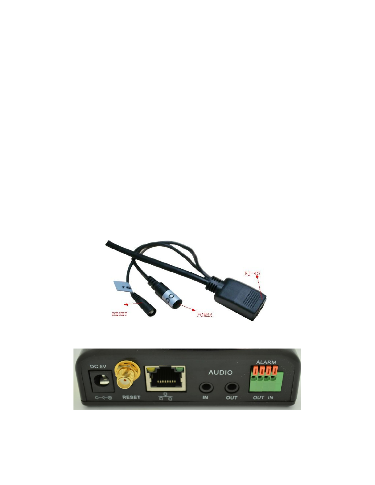
Follow the steps below to set up your camera hardware. Make sure to follow each step carefully to ensure that the camera operates properly.
1. Install the Wi-Fi antenna by twisting the antenna connector clockwise to the camera’s antenna port (for
wireless models).2. Plug the power adapter port into camera ’s power supply port. This may be external (outdoor models) or
internal (indoor models) depending on which camera you purchased. 3. Plug the network cable into the RJ-45 connecter which is found either on the external wiring (foroutdoor cameras) or on the back of the camera (for indoor cameras), and plug in the other side of the RJ45 cable to a port on your router/switch.
4. It takes approximately 30 seconds to boot up the camera, you will see the camera swivel automatically
a few seconds after it is plugged in, this indicates the camera has successfully powered on.5. When the camera is correctly powered on and the network cable is connected properly, the green LED
on either the RJ-45 connector of the camera (for outdoor models) or the connector on the back of the camera (indoor models) will remain solid. The yellow LED should continue to flash.
Figure 3.1 – Outdoor Camera Wiring (your camera may be slightly different) Figure 3.2 – Indoor Camera Rear Ports (your camera may be slightly different) support@agasio.com Page | 5 713-893-4514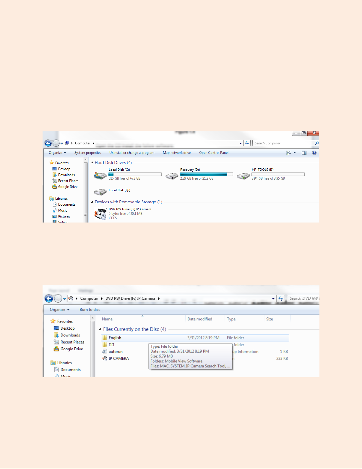
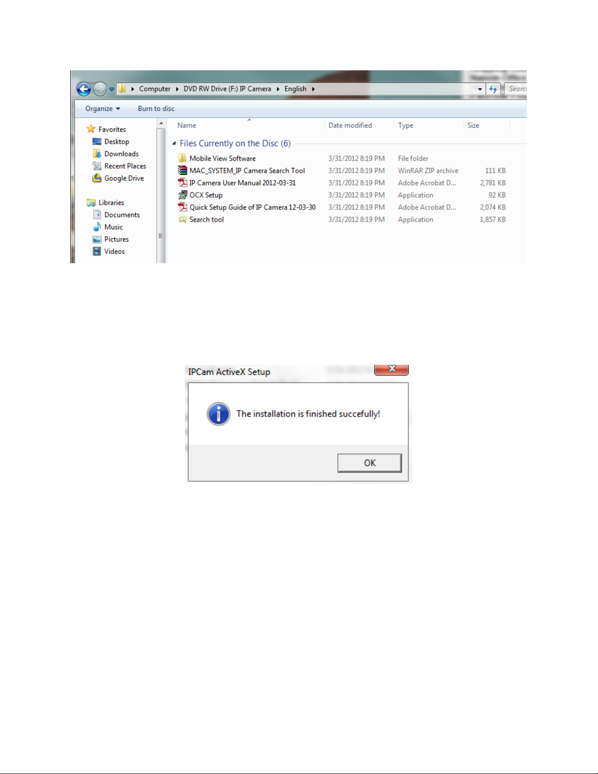
1. Before continuing, we must first run and install the file named “OCX Setup.” Double -click this file, and a dialogue box should appear that reads, “The installation finished successfully!” Press OK.
2. Next, click the application named “Search tool.” The program will begin to run automatically from the CD. If you would like, this software can be copied to your desktop. This will be continued in the next section, “Software Operation.”
support@agasio.com Page | 7 713-893-4514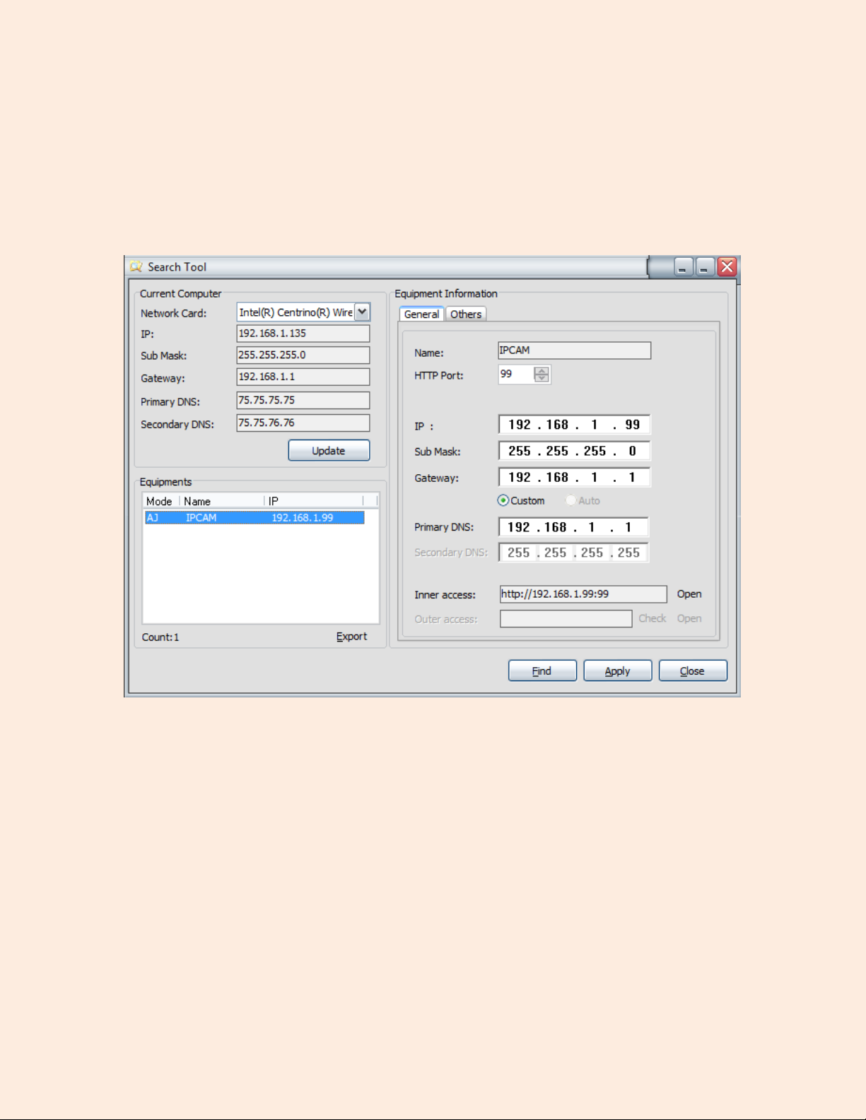
Network (LAN) of the router the computer is connected to. Please make sure the computer you are using Search Tool on is connected to the same router that the camera is connected to.
sup p o rt@ ag asio . co m P ag e | 8 7 1 3 - 8 9 3 - 4 5 1 4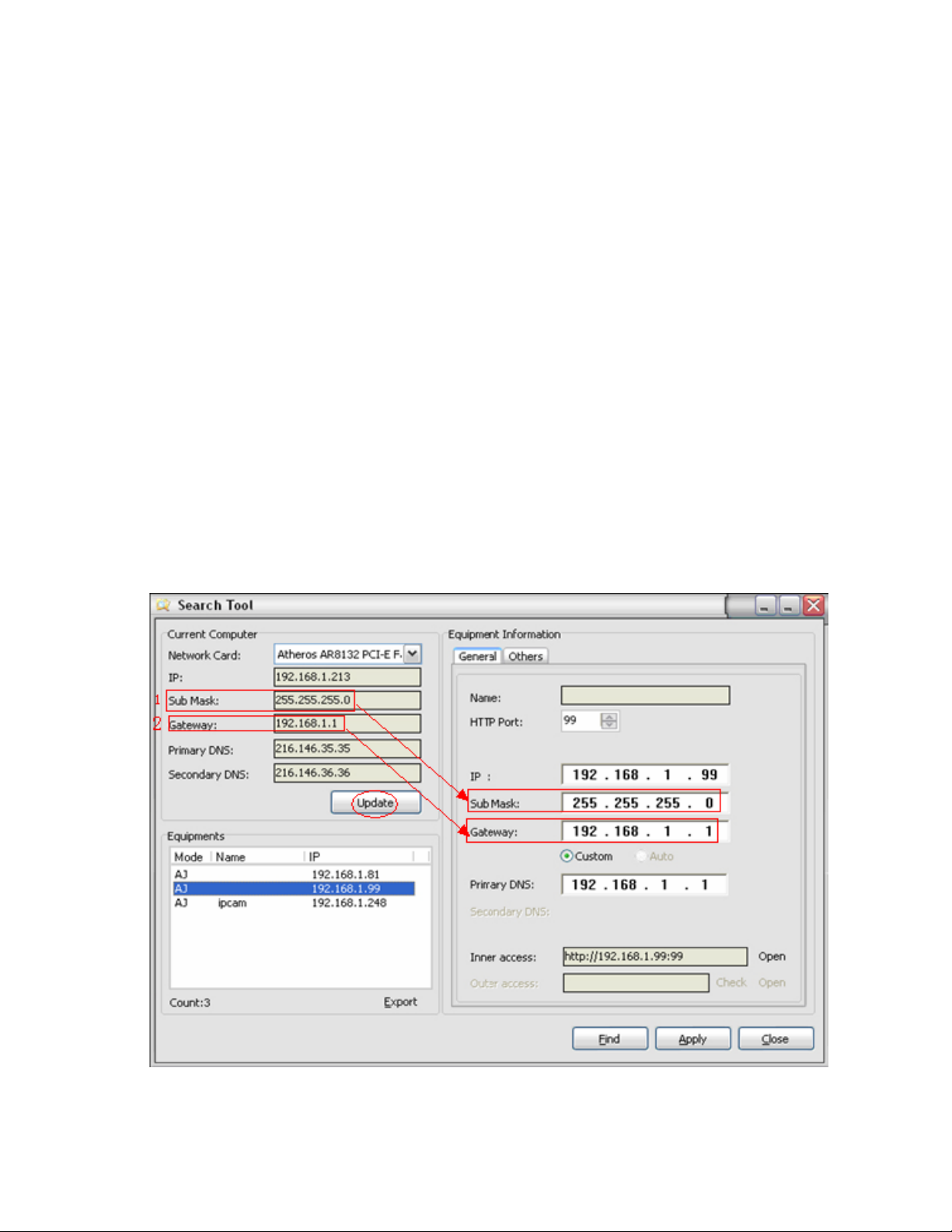
No IP Cameras can be found within the Local Area Network (LAN). After about a 1 minute search, the Equipment List will not show any IP addresses or cameras. If this happens we recommend firstly clicking the “Find” button at the bottom of the program to see if any cameras show up. If no cameras show up, try closing the software and re-opening it again to see if any cameras are detected.
Second ScenarioThe IP Cameras have been detected within the Local Area Network (LAN). All the IP Cameras will be listed and the total number is displayed in the “Equipment” field as shown in Figure 5.1.
1. Current Computer – Fields under this section indicate the Computer’s IP Address information. 2. Equipment information – This section indicates the IP camera’s IP Address information. 3. If you find that the camera’s “Subnet Mask”, “Gateway”, “DNS Server” is not the same as yourcurrent computer IP address information, you need to change the camera’s IP address. This is done easily within the Search Tool by clicking the “ Update ” button, seen in Figure 5.2 below. You will be
prompted to confirm and enter administrative information. By default, the username is “admin” with no password. The camera will then reconfigure itself and will disappear, then reappear in the list.
Figure 5.2 – Make Sure Your Subnet Mask, Gateway, and Primary DNS Matches the Camera’ s support@agasio.com Page | 9 713-893-4514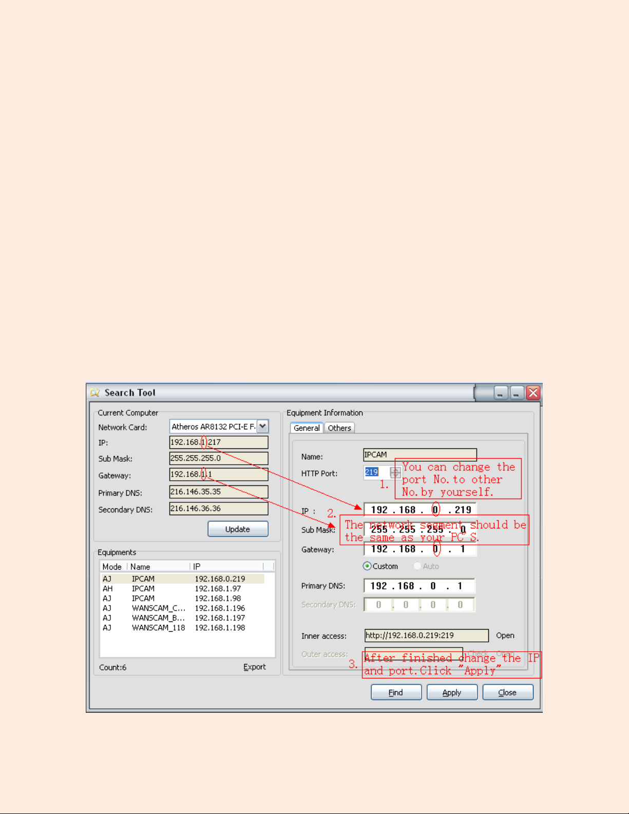
Once your camera’s IP address’ Subnet Mask, Gateway, DNS Server is the same as your PC or router, you need configure the camera’ s network parameters manually.
IP address: Fill in the IP address assigned and make sure the first three sections of the IP are the same
as the IP listed under the “Current Computer” section. For example, in Figure 5.2 , the first three sections of the IP that need to be entered under “Equipment Information” where the “IP” field is should be
192.168.1. These numbers were taken from the IP field under “Current Computer.”Subnet Mask: The default subnet mask of the equipment is almost always: 255.255.255.0. You can find the subnet mask under the “Current Computer” section of the software in the field “Sub Mask.”
Gateway: Just like the IP address, make sure all four sections of the Gateway are exactly the same. For example, in Figure 5.2 , the Gateway IP that should be manually typed in is 192.168.1.1. This information is found under the “Current Computer” section in the field “Gateway.” The G ateway is the LAN IP of your router.
Primary DNS: IP address of ISP network provider. You can also set it as the same as the Gateway. For example, in this case it would be set as 192.168.1.1.
HTTP Port : You can enter a custom port number in this field for the camera; default port number is set to
99. You can change the port number to any number you would like, such as: 98, 211, 9999 etc. Figure 5.3 – Manually set the camera’s information to that under the “Current Computer” section sup p o rt@ ag asio . co m P ag e | 10 7 1 3 - 8 9 3 - 4 5 1 4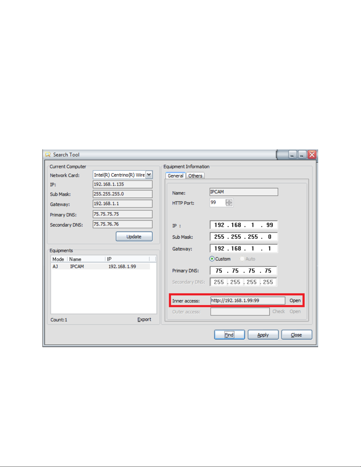
You can access the camera using Search Tool, IP Camera Tool or IE, Firefox, Safari, Google Chrome or other standard browser directly.
1. In Search Tool, there is a field that reads “Inner access.” This lists the current Local IP Address of the camera. This IP address can be entered in any browser’s URL field to bring up the camera
login. You can also push the button on the right of the field that reads “Open.” This will open the camera up in your default browser. Figure 5.4 – The camera login page can be opened using the “Open” button2. To access the camera by IE Browser directly, just type the camera’s IP address, for example, if the camera’s IP address is 192.168.1. 99:99, it would be typed as http://192.168.1.99:99.
support@agasio.com Page | 11 713-893-4514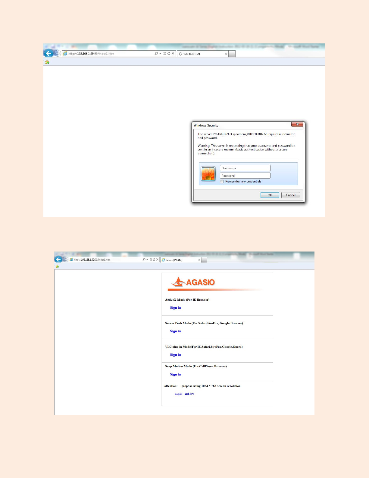
(1) “ Active Mode ” (For IE Browser): available for Internet Explorer 6.0 and above. (2) “Server Push Mode”: available for Firefox, Safari, and Google Chrome browsers.
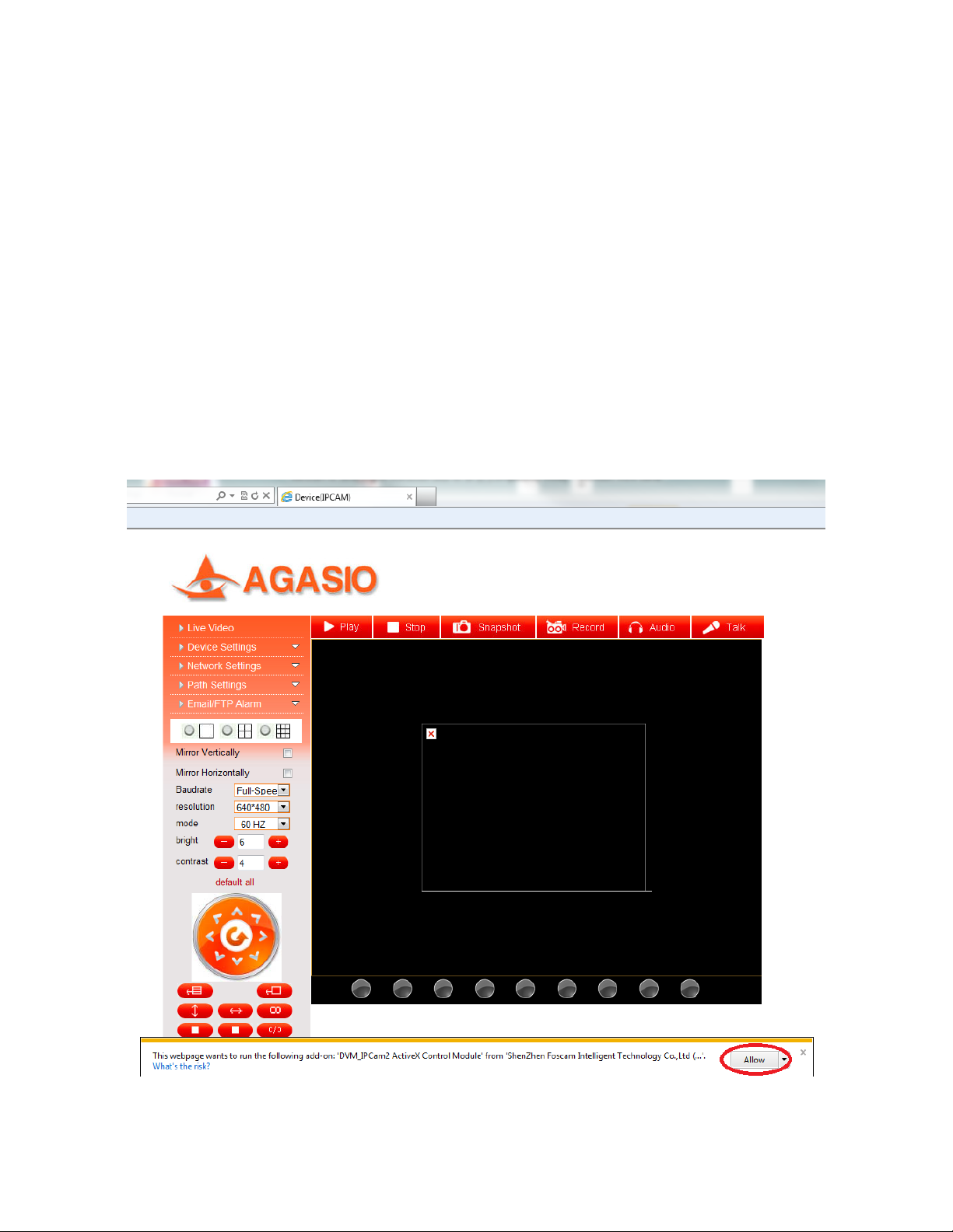
(3) “Snap Motion Mode”: available within mobile phone browsers. 7. Viewing with Internet ExplorerChoose “ Active Mode ” (For IE Browser), and sign in. When logging into the camera for the first time, you may receive an ActiveX prompt as seen in Figure 7.1 . You will need to click “Allow” for Internet Explorer to confirm running the IP Camera software add-on. The page will refresh and you may be asked to login
once again. Once logged in again, you should see live video. Figure 7.1 – If you see a red box and a prompt as seen above, please click “Allow” or “Run” support@agasio.com Page | 13 713-893-4514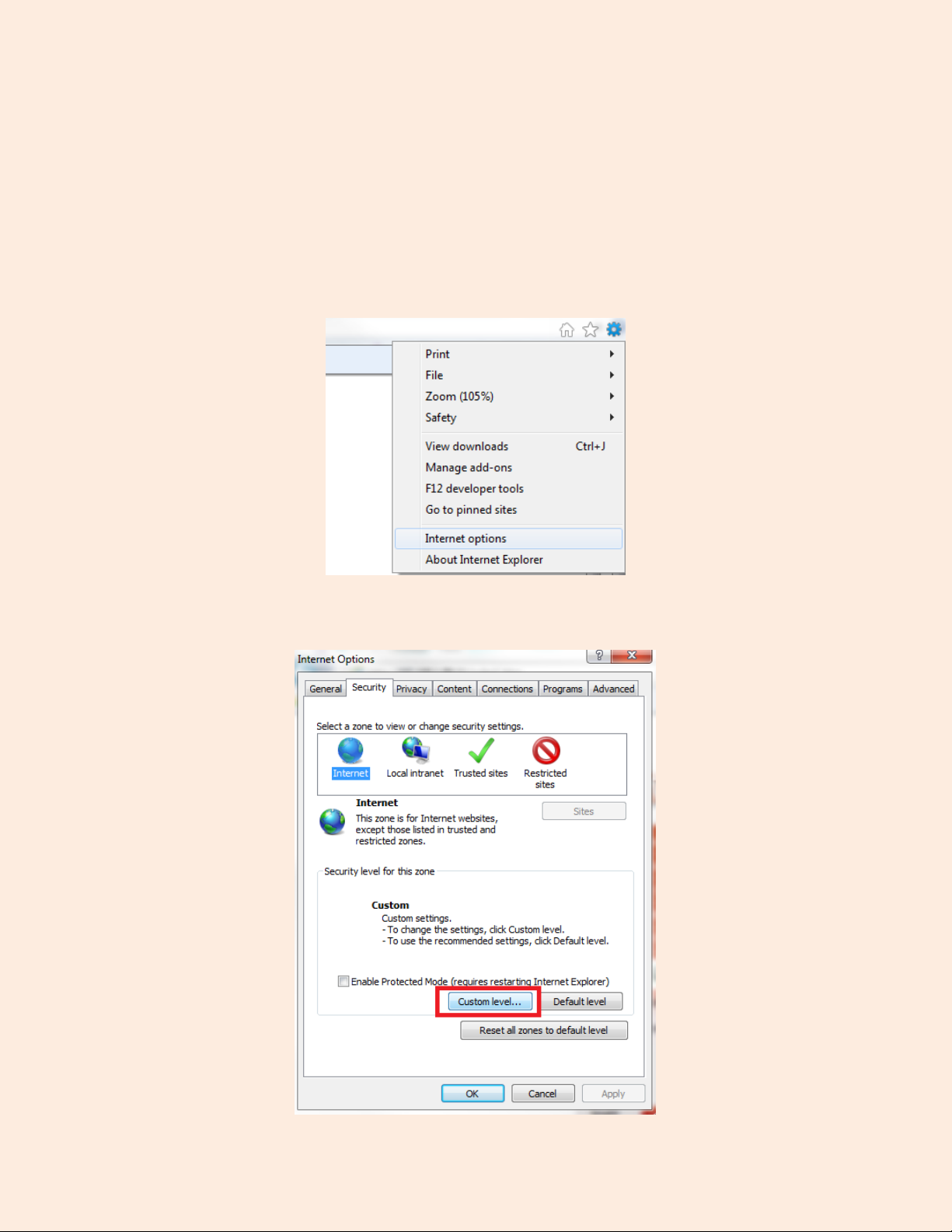
If there is still no live video after confirming the ActiveX add-on module or if you continue to get a black
screen with the red “X” at the top left , you will need to try and enable the ActiveX options of Internet Explorer’s security settings using the following steps:
Note: You may need to disable your firewall firstly to see if this is not causing the issue.You will need to change the ActiveX settings within Internet Explorer by clicking “Tools” or the “Gear”
symbol on the top bar, and scrolling down to the option named “Internet Options”Next, click on the tab at the top that reads “Security,” and click on the button near the bottom that reads “Custom Level.”
sup p o rt@ ag asio . co m P ag e | 14 7 1 3 - 8 9 3 - 4 5 1 4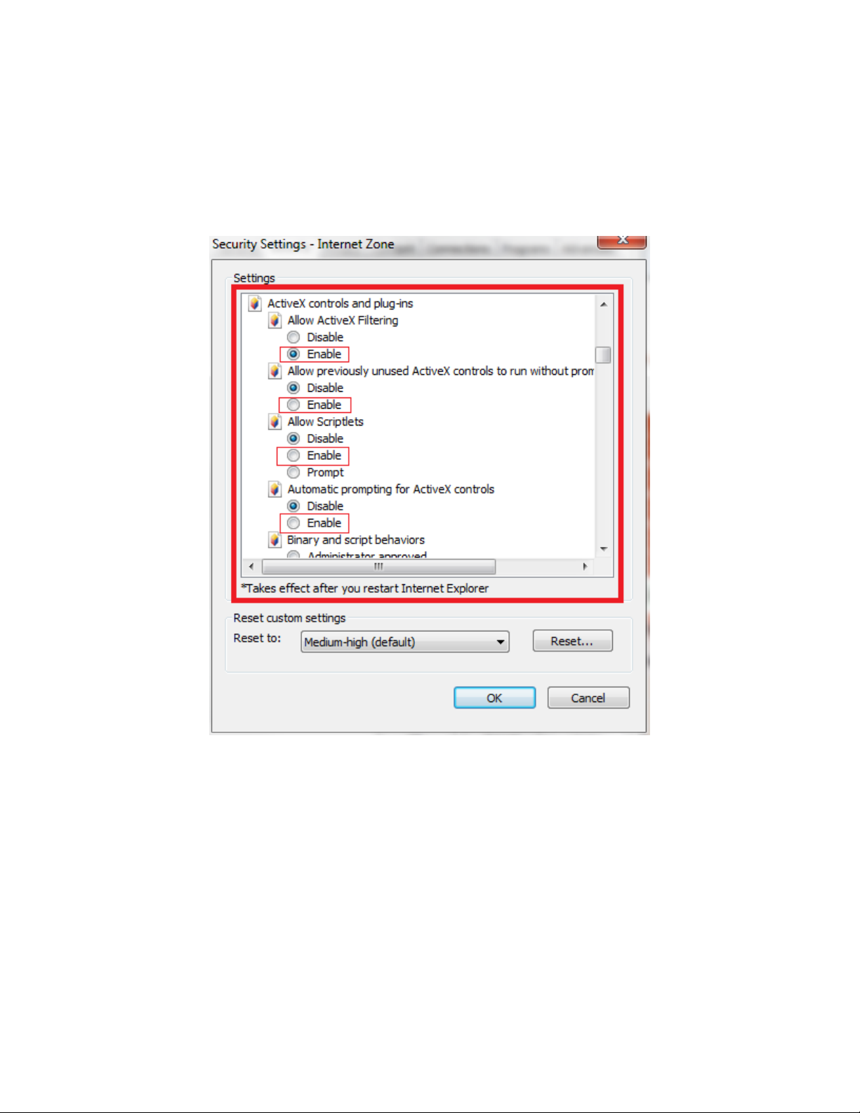
This will take you to the Advanced Settings where you can manually change the ActiveX control options.
Scroll down on this screen to where it reads “ActiveX control s and plug- ins” as the parent option, and set the child options to “ Enable .”
The most important options to keep enabled are the following:Enable: “ Download unsigned ActiveX controls ” Enable: “ Initialize and script ActiveX controls not marked as safe ” Enable: “ Run ActiveX controls and plug-ins ”
support@agasio.com Page | 15 713-893-4514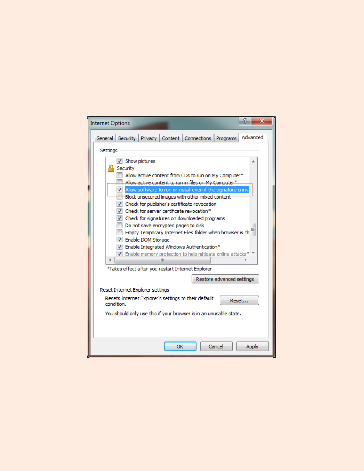
Once on the “Advanced” tab, scroll down to find the parent category named “Security.” Check the option which states “Allow software to run or install even if the signature is invalid.” This is
pictured below:Note : Make sure that your firewall or anti-virus software is not blocking the camera software or ActiveX. If you are unable to view live video, please try disabling/closing your firewall or anti-virus software and trying to log into the camera again.